Understanding Coriolis Meter Technology
History, Theory, Function and Limitations
Why Coriolis Meters?
Understanding Coriolis meter technology starts with knowing their capabilities: mass flow measurement, high accuracy and no moving parts design. Most flow meter technologies measure volume or velocity while Coriolis Meters directly measure mass. Since many consumers purchase media by weight, direct measurement of mass appeals to producers since most gas or fluid properties change when subject to temperature or pressure variations. Volume fluctuates based upon conditions, unlike mass, which makes these meters ideal for custody transfer applications. We like to say that “mass is mass” whether on the beach, a mountain or the moon. Coupled with the high accuracy of up to .1%, Coriolis meters serve as the go to selection when accuracy matters most. Last, though certainly not least, Coriolis meters contain no moving parts and require little or no maintenance. Install the instrument and let it run without the high cost of maintenance.
History of the Coriolis Force
The next key to understanding Coriolis meter technology involves the history behind their development. Gustave Gaspard de Coriolis discovered the ‘Coriolis Effect’ when observing cannon balls launch north to south or south to north. Each ball appeared to move in a curved trajectory bending slightly toward the East. The opposite effect occurs in the Southern hemisphere with deflection bending toward the West. The rotation of the earth and the location of the observer caused the visual effect. Therefore, the ‘coriolis force’ exerts itself on objects moving within a rotating frame of reference such as the earth. Since Gustave’s observation in 1835, scientists applied the use of the Coriolis Effect to ballistic missile trajectories, hydraulics, machine performance, and ergonomics as well as ocean and atmospheric circulations.
Despite the popular urban legend, a person cannot observe the Coriolis Effect by watching a toilet flush or a swimming pool drain. The movement of fluids in these situations depends upon the manufacturer’s design or outside forces such as a strong breeze or movement of swimmers.
Visualizing the Coriolis Force
A Merry-Go-Round Example
When sitting on the rotating frame of the merry-go-round, the ball (mass) appears to curve as it passes between the children. From the inertial view, above the rotating frame, the ball (mass) passes in a straight line as shown in the graphic below. To better understand this concept, notice that the child set to receive the ball moves away from the path of the ball. The directional path of the ball simply continues in a straight line. The rotating frame gives the appearance of a curved trajectory. Therefore, the force exists as an ‘apparent’ force rather than an actual force.
A Garden Hose Example
Here, the sway of a hose sets up the rotational motion with no fluid present. Observe the even swing of the hose. Notice that the hose or pipe flexes when flow starts to travel through it while continuing to sway back and forth. The effect appears greater as flow increases. As the amplitude of the oscillation rises, the effect appears greater still. Although not obvious from the video, the rotational velocity (speed of the swing) or operating frequency also impacts the degree of flexing that occurs within the pipe.
The Science Behind the Coriolis Force
Newtonian laws of motion forms the next key to understanding Coriolis meter technology. F = Ma refers to a mass moving in a single direction. The theory behind Newton’s laws of motion evolved by incorporating an oscillating acceleration. The inertial Coriolis force acts perpendicular to the direction of motion and to the axis of rotation. This graphic demonstrates the application of the science behind the ‘Coriolis Force’ as a gas or liquid travels within a pipe:
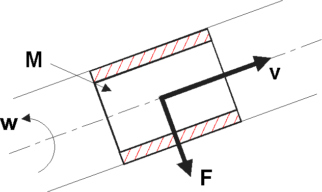
The graphic represents the mass (M) of the fluid or gas moving through a pipe (v) while a perpendicular force (F) simultaneously acts on the medium when exposed to oscillation (w).
The Operating Principal of Coriolis Meter Technology
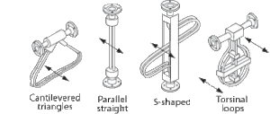
To better understand Coriolis meter technology’s operating principal, let us examine the structure and function of the instrument. As shown in the graphic, most Coriolis meters utilize a variety of dual tube designs. The more common tube shapes include u-tube, diamond and omega shape. Drive coils, mounted on the tubes, energize them. This energy vibrates the tubes toward and away from each other at a certain rate called the resonant frequency with no flow present. (photo taken from www.isa.org)
The Coriolis force, acting on the mass of the fluid, causes a slight deflection of the tubes as flow moves through them. Pick up coils constantly measure the distance between the tubes creating a sine wave. The sensor then computes the time difference or Delta T between the sine wave zero crossing for pickup one and pickup two. The Delta T is directly proportional to the mass moving through the tubes. An electronic controller paired with each flow sensor performs instantaneous calculations.

Density and Temperature Outputs
Coriolis meters provide density and temperature outputs due to the inherent capabilities of the design. The stiffness and mass of the tubes determines the natural resonant frequency produced through vibration. Since the volume of fluid in the tubes remains constant, a change in the density of the fluid causes a change in mass. When the mass inside the tubes change, the pickup coils detect the resulting resonant frequency change. Because the change in density of the fluid directly relates to the change in frequency, the electronics simply translate that to a density output. Mass measurement requires no temperature reading. However, every Coriolis meter includes temperature measurement to improve accuracy and repeatability. For this reason, most manufacturers make the output available.
Limitations – Thin Wall Tubes
Most Coriolis meter manufacturers order special runs of thin wall tubes in order to generate sufficient tube vibration and signal strength required for the electronics to read. Thin wall tubes energize easily and vibrate readily. This issue creates a range of related limiting factors for the instruments such as: 1) poor corrosion / erosion allowance, 2) increased signal manipulation, 3) inability to achieve high pressure ranges and 4) reduced alloy selection. Let’s examine the issues.
- When the fluid medium contains particulate like sand, thin wall tubes erode. Other fluid mediums attack certain alloys over time causing corrosion. Once the tube ruptures, the non-repairable instrument permanently fails.
- While thin wall tubes produce a better signal with less energy, it is still generally weak when installed near other noisy machines that disturb the signal. For this reason, many Coriolis meters perform better in a laboratory setting. Further, many instruments depend on signal manipulation to clear the noise and environmental chatter.
- Pressurized tubes require containment to prevent hazardous conditions in the event of rupture. Wall thickness plays an essential role in containing the high pressure fluid or gas. For this reason, many Coriolis meter manufacturers struggle to achieve pressures above 5,000 PSI.
- Manufacturers limit alloy selections simply because they must re-engineer the instrument for each type of alloy utilized. The characteristics of alloys range from soft to rigid making some easier and others more difficult to develop in a thin walled design.
Limitations – Other
The measurement section in most Coriolis meters extends to the flanges which creates a variety of accuracy challenges related to process born disturbances, misaligned piping and temperature stresses.
- Process born disturbances caused by pulsating flow or pipe bends often negatively affects the accuracy of the reading.
- In situations where a misalignment of the pipe exists, an installer may use a sensitive instrument like a Coriolis meter to solve the problem. Even a minute tweak of the tubes causes changes throughout the measurement section impacting the quality of the readings.
- Many areas of the world experience significant temperature fluctuations between day to night and throughout the year. These fluctuations not only impact the piping. It also impacts the tube structure of a Coriolis meter particularly when the measurement section extends to the flange. Again, this leads to reduced accuracy.
- The average Coriolis meter may cost more than two times the amount of a competing mechanical technology. It often compels end users to weigh alternatives. While the upfront cost runs higher for Coriolis flow meters, the total cost of ownership remains much lower because the instrument contains no moving parts and therefore, little or no maintenance.
In Summary
Some key benefits of Coriolis meters include high accuracy and mass flow measurement which makes them ideal for applications involving weight and custody transfer. They contain no moving parts which produces a virtually maintenance free instrument. The meters solve applications with wide process parameters, temperatures, pressures, viscosities, mediums and flows with ease. Manufactures build temperature and density measurements into the electronics. While not specifically addressed in this article, most Coriolis meter electronics feature advanced flow computing generating reporting on temperature, density in addition to standard outputs available with other technologies.
Limitations include the upfront cost of purchase which may double the amount of a competing technology. When evaluated over the life cycle of the installation, the elimination of parts and maintenance reduces the total cost of ownership over time. Further, the use of thin wall tubes reduces alloy selection and accuracy in many field installations. We hope this article served to broaden your understanding of Coriolis meters.
Follow the hyperlink for more information about the Coriolis meters from Rheonik available through MJ Systems or contact our office should you desire application support!